
Wiring A Light Circuit
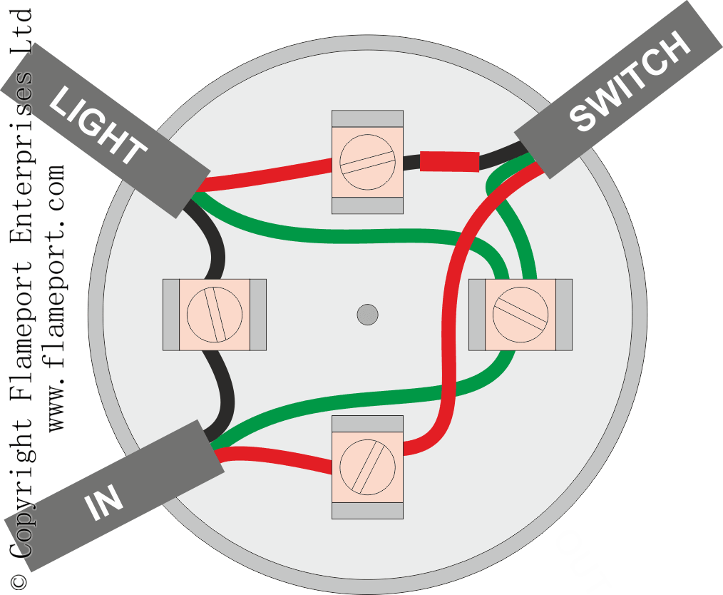
This is an alternative way of wiring a lighting circuit. Instead of taking the feed wire from the consumer unit to the ceiling rose it is taken to the switch. The permanent live wire is wired into the switch and the switched live into the switched live terminal. The neutrals are connected together using a terminal connector. You can also see.

Wiring a Simple Lighting Circuit (2022)
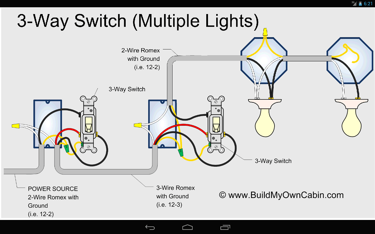
Multiple Light Wiring Diagram. This diagram illustrates wiring for one switch to control 2 or more lights. The source is at SW1 and 2-wire cable runs from there to the fixtures. The hot and neutral terminals on each fixture are spliced with a pigtail to the circuit wires which then continue on to the next light.
Wiring Lighting Circuit Diagram Wiring 6 recessed ligthing with two 3way switches It shows
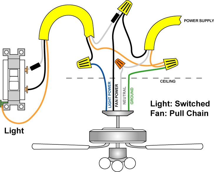
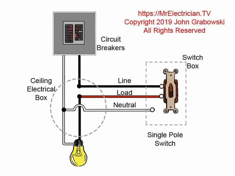
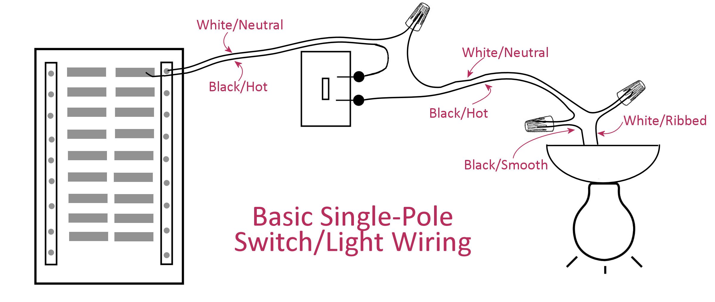
Typical electrical wire for home use comes in an insulated sleeve and consists of three wires. A black wire carries the electrical current and is therefore commonly known as the "hot" wire. There is a white wire that is the "neutral," and, finally, a bare copper wire that is the ground wire. When electrical wires are joined together the.
1 Way Lighting Circuit Wiring Diagram
In effect this is exactly the same wiring as the diagram on the top of the page, but with the utilisation of the flat Twin&Earth cable. Once tested and connected to the live supply, the lighting circuit will be operational. Extending the lighting circuit. Now you know how to wire a basic lighting circuit with one light switched at one point.
Everything You Need To Know About Light Wiring Wiring Lights Diagram Cadician's Blog
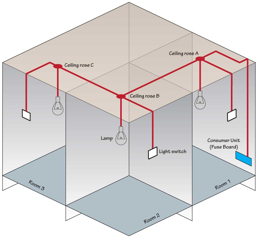
Radial (or junction box) wiring. Picture 2 below shows a typical radial (or junction box) lighting system, a two-core and earth cable runs from the consumer unit to a series of junction boxes - one for each lighting point (ceiling rose). From each junction box a separate cable runs to the light and another runs to the switch.
Lighting Circuits Using Junction Boxes Light Wiring Diagram Cadician's Blog
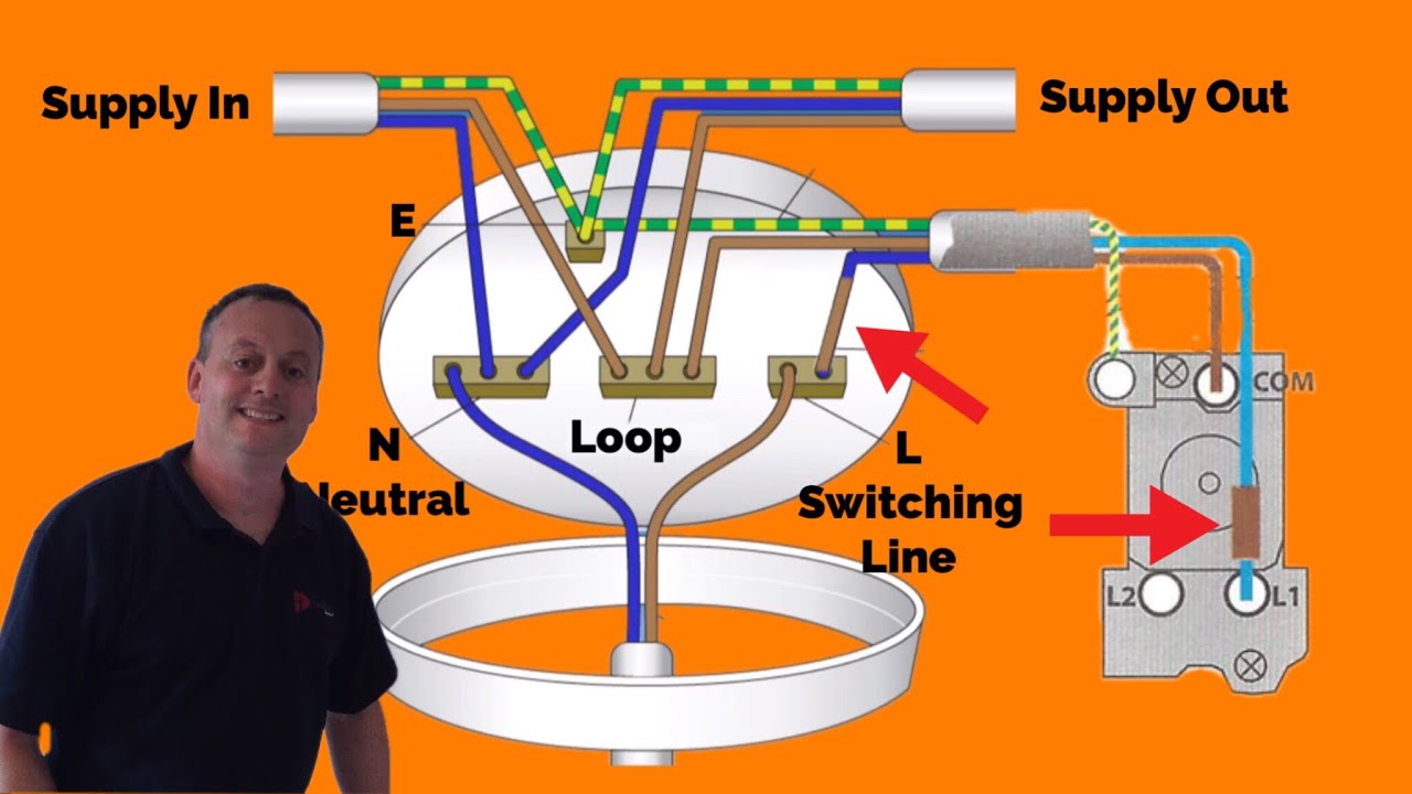
Types of Lighting Circuits. In a domestic situation there are 2 different types of lighting circuit, the traditional junction box setup and the newer loop in setup. The loop in setup, shown below, takes power from the consumer unit to the first ceiling rose. It is then taken from the ceiling rose, through the switch and back to the ceiling rose.

Basic Wiring For A Light Switch
There are three basic types of wiring diagrams: Wiring: Depicts electrical devices as drawings or pictures connected by lines representing wires. Wiring diagrams show specific electrical connections. Pictorial: Shows how components are related to others on the same circuit, but contains less detailed information about electrical connections.
Light Circuit Wiring Diagram
A lighting wiring diagram is a visual representation of the electrical wiring in a room or home. It displays the layout of the electrical components as they are connected including light switches, outlets, light fixtures, conduits, and junction boxes. It's used by electricians, contractors, and do-it-yourselfers when installing or repairing.
2 Way Lighting Circuit Diagram
The right way to wire a standard single-pole light switch depends on where the switch is located relative to the light. The diagrams below show the various options. Light at center of circuit. This single-pole switch controls a light where the wire from the source goes directly to the light. Switch between source and light.
2 Gang 2 Way Lighting Circuit Wiring Diagram Wire Light Circuit Household Electrical Switches
The Basics of Home Electrical Wiring Diagrams:. How to Wire a Wall Outlet - Example of Outlet Wiring when there are more than one cable from the electrical circuit. Fix Light Fixture and Switch Wiring Problems; Fix a problem with a light that your trying to install. Wiring Connections for Light Fixtures and Switches.
Basic Wiring Diagrams For Lights
Step 1: 3 Volt Basic LED Circuit With 10 Ohms Resistor. The above diagram shows a 3V LED circuit, in this circuit there are two AA cells are used. When you are operating an LED with 3V you have to use minimum 10 ohms resistor . For more details visit Simple Basic LED Circuit. Ask Question.
Basic Lighting Wiring Diagrams
6. Disengage your light from its wires. You should see plastic caps, called wiring caps (also called a wire nut), with two wires running into each cap. One wire will come from the light, the other from the main electrical circuit of your house. Disengage the wires by twisting the wiring cap until it comes free.
Light Switch Wiring Diagram 1 Way
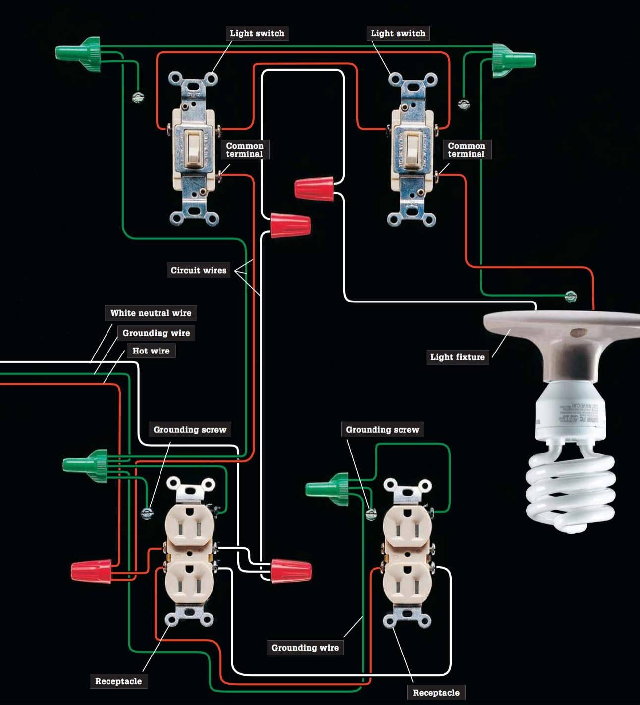
The important components of typical home electrical wiring including code information and optional circuit considerations are explained as we look at each area of the home as it is being wired. The home electrical wiring diagrams start from this main plan of an actual home which was recently wired and is in the final stages.
Basic Light Circuit Diagram
Four or more switches. Both of the three way switching diagrams can be extended to four, five or even more switches. All of the additional switches are internediate types (4 terminals), and connect into the middle of the circuit in exactly the same way. A dimmer switch can be used on any of these circuits, but for two switches and above, only.
Residential Lighting Circuit Diagrams
Cable size: 1.0mm TPS or 1.5mm TPSI'll be uploading a few 'Basic' videos for beginners while filming more advanced videos.WARNING: DO NOT ATTEMPT TO DIY ELEC.
How To Wire A House Lighting Circuit
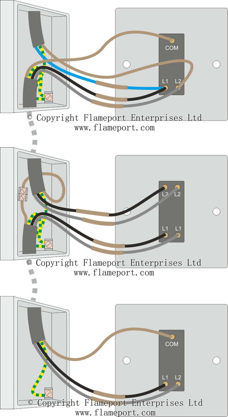
A 2-Way Switch wiring diagram depicts the wiring that allows incoming and outgoing circuits to be connected in a way that can be turned on and off from either end. Two-way switching is usually between a two-way radio and a transmitter/receiver. This circuit is a quick way to show you how a two-way switch works. 1.